
MyTechDailyNews Hardware Buyer's Guide: Open-Loop LLC Control with TPLD2001-Q1
Hardware decisions often begin with a tolerance question: can an LLC converter remain acceptable without active regulation? The reference material contrasts a closed-loop controller capable of a precise ±3% regulated output with an open-loop case where a ±10% unregulated output may be acceptable. If that tolerance fits the product, the board can move away from unnecessary closed-loop functions and toward a simple low-cost control method built around programmable logic.
For a MyTechDailyNews Hardware audience, the interesting part is not that open-loop operation exists, but which functions must survive the simplification. The same reference describes high-power isolated applications using a half bridge or full bridge on the primary side according to voltage and power level, and notes that synchronous rectification is often required for good efficiency, particularly at low output voltages.
Feature checklist: what an open-loop controller still must do
An open-loop implementation is not "no control." The mandatory set still needs a primary-side power stage drive, soft start, an enable input, and over-current protection (OCP) with cycle-by-cycle current limiting, either in hiccup mode or with latch-off. Optional functions may include a power-good output, over- and under-voltage lockout, and driving the synchronous rectifiers.
The Texas Instruments programmable logic device (TPLD) family is presented in the source material as a cost-effective way to realize that open-loop feature set.
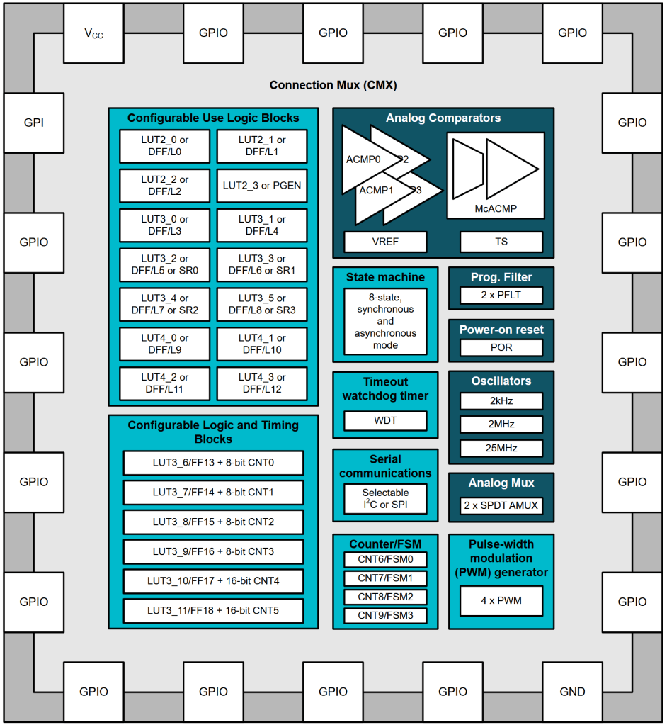
Figure 1 — TPLD2001-Q1 block diagram, showing logic blocks, internal oscillators with a clock frequency up to 25MHz, a state machine, and analog comparators that align with an open-loop LLC controller. Source: Texas Instruments
Control-signal architecture: internal PWM or a logic-generated waveform
At lower switching frequencies, the device’s internal pulse-width modulation (PWM) generators may be used. At higher frequencies, the article describes building a custom control-signal generator with logic cells. One implementation is a classical ring buffer made from configurable one-shot blocks, producing two inverted primary-side signals and adding dead time.
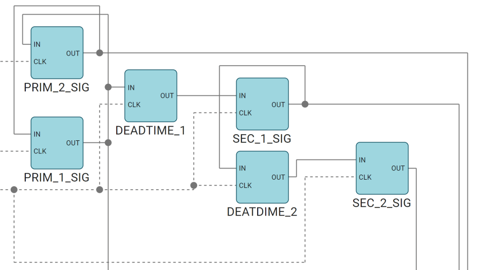
Figure 2 — Example timing structure generating two primary-side control signals and two synchronous-rectifier control signals on the secondary side, with adjustable dead bands between primary and secondary inside a single TPLD2001-Q1. Source: Texas Instruments
Synchronous rectification without a dedicated SR controller
The article states that, with this arrangement, there is no need for a specialized synchronous rectifier controller. A comparator channel can measure the primary-side current, then enable synchronous rectification as soon as the converter input current rises above a decision threshold.
Figure 3 gives a design example using synchronous rectification without a specialized controller. It also notes that LMG2104-Q1 integrated half bridges simplify the TPLD implementation because those devices take care of the required dead time for the primary side by themselves.
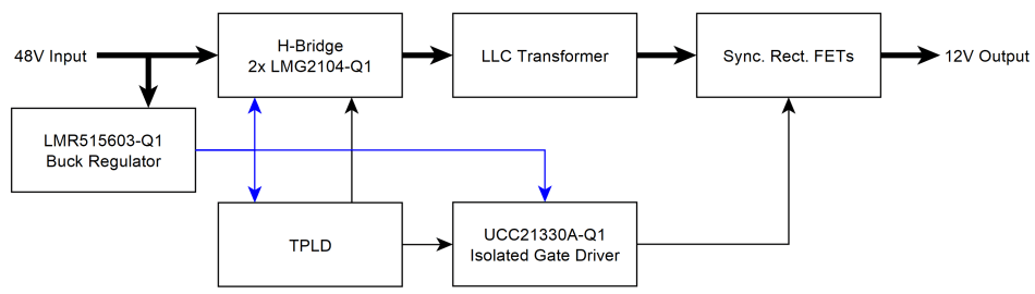
Figure 3 — Overview of the example design in which the TI TPLD2001-Q1 acts as the controller. Source: Texas Instruments
Protection behavior: OCP, soft start, enable, and lockout expansion
OCP can be achieved with the internal comparators, disabling switching if the primary-side current becomes too large. The available logic gates allow cycle-by-cycle current limiting by skipping cycles when the current reaches a set limit.
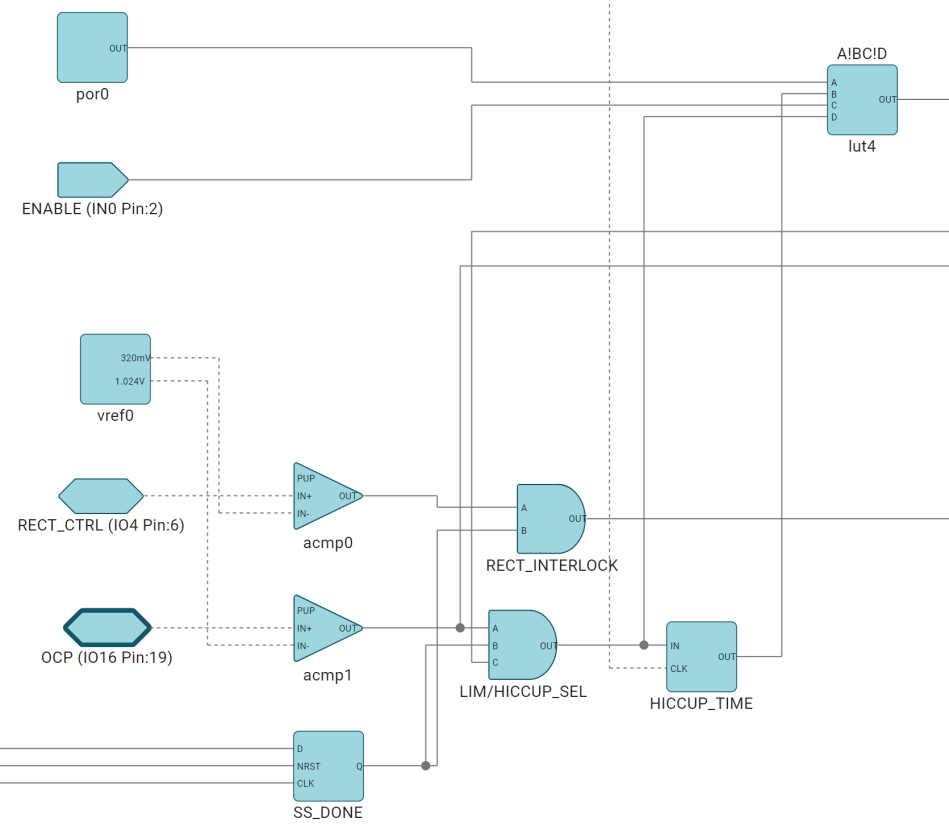
Figure 4 — Example current-limit implementation that fits within the TPLD2001-Q1. Source: Texas Instruments
After a defined period, the logic can enter hiccup mode or latch-off, behaviors the article says can be implemented with one-shots or one of the TPLD counters. During soft start, synchronous rectification is disabled so that no unwanted current flows from the output back to the converter input. The enable input resets the device, causing it to run through soft start when enabled. Devices with several analog inputs can also add under-voltage lockout and over-temperature protection.
Data takeaways: frequency limits, dead time, and efficiency trade
Programmable logic has constraints, but the source material argues that many are easy to manage. The fixed-period counter value limits internal PWM generators to <100 kHz. Because the open-loop LLC topology does not require duty-cycle or frequency variation, designers can synthesize their own control-signal generator from available logic cells. The 25MHz clock is described as high enough to create suitable dead times and output signal frequencies up to about 500 kHz. Higher frequencies are possible, but the dead time then occupies a larger share of the switching cycle and efficiency can fall.
When synchronous rectifier controllers and integrated power stages handle dead time themselves, the article says that efficiency penalty is no longer an issue.
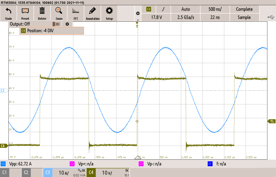
Figure 5 — Waveform plot from the design example, showing the switch node and current waveform. Source: Texas Instruments
Device comparison: TPLD2001-Q1 versus TPLD1202-Q1
If a design needs no more than two analog inputs, the article notes that a smaller device such as the TPLD1202-Q1 may be an option. It adds a caution: the TPLD1202-Q1 has only one comparator, so inputs are multiplexed and are too slow for OCP. By contrast, the discrete analog comparators available within the TPLD2001-Q1 are fast enough to implement OCP and can support other features, such as the simple synchronous rectification control described earlier.
| Buyer criterion | TPLD2001-Q1 | TPLD1202-Q1 |
|---|---|---|
| Analog comparator behavior | Discrete analog comparators are described as fast enough for OCP and synchronous rectification control. | Only one comparator; inputs are multiplexed and described as too slow for OCP. |
| Fit for the example control chain | Used in the design example with primary-side and secondary-side signal generation. | Considered when no more than two analog inputs are needed. |
| Cost-sensitive interpretation | Preferred when multiple fast analog threshold features are required. | The source notes it may fit cost-sensitive applications when OCP is the only required analog feature, while also warning that multiplexing is too slow for OCP. |
Common misreadings
- Misreading: Open-loop means protection can be omitted. Reference correction: Soft start, enable, OCP, and primary-stage drive are still listed as mandatory functions.
- Misreading: Synchronous rectification requires a separate controller. Reference correction: The article describes a comparator channel measuring primary-side current and enabling synchronous rectification above a threshold.
- Misreading: The internal PWM ceiling is the ceiling for all programmable logic control. Reference correction: Logic-based signals can reach about 500 kHz, with dead time becoming the limiting efficiency trade.
- Misreading: The smaller TPLD1202-Q1 simply replaces the TPLD2001-Q1 at lower cost. Reference correction: Its single comparator path is multiplexed and too slow for OCP, although cost-sensitive interpretations depend on the exact analog requirement set.
Action advice for hardware buyers
- Confirm whether the system needs a precise ±3% regulated output or can accept a ±10% unregulated output.
- Check mandatory control features first: primary-stage drive, soft start, enable, and OCP with cycle-by-cycle limiting.
- Use internal PWM only when the fixed-period limit below <100 kHz is adequate.
- If a higher switching target is needed, evaluate a logic-based generator up to about 500 kHz, then verify dead-time percentage, not just maximum clock speed.
- When LMG2104-Q1 integrated half bridges can manage primary-side dead time, prioritize the simplified system path described in the example.
- If OCP or synchronous rectification depends on fast analog thresholds, favor the TPLD2001-Q1 comparator implementation; if the design has no more than two analog inputs, review the TPLD1202-Q1 trade carefully.
- For requirements such as bidirectional operation or higher switching frequencies, consider the TI MSPM0 microcontroller option mentioned in the conclusion.
Closing note
For MyTechDailyNews Hardware readers, the value here is decision clarity rather than component hype. The Texas Instruments reference positions the TPLD family as flexible enough for relatively complex converter control mechanisms, especially when an LLC application can live without a closed control loop. If voltage tolerance, frequency behavior, dead time, and analog threshold speed are verified against the device limits, the low-cost open-loop approach can be a sensible fit; if the overall specification exceeds those limits, the cited alternative is a TI MSPM0 microcontroller.